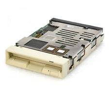
Fujitsu M2512A
3.5" MO-Laufwerk intern SCSI 50-Pin für 128 und 230 MB MO Medien
Numéro d'article: 002994
Description du produit
Switch SW1
Select SCSI ID
        Keys	1	2	3	SCSI ID
	        OFF*	OFF*	OFF*	0
	        OFF	OFF	ON	1
	        OFF	ON	OFF	2
	        OFF	ON	ON	3
	        ON	OFF	OFF	4
	        ON	OFF	ON	5
	        ON	ON	OFF	6
	        ON	ON	ON	7
SCSI bus parity
       Key 4	ON(*)   Enabled
                OFF	Disabled
Synchronous Data Transfer Request Mode
       Key 5    ON	Enabled
         	OFF(*)  Disabled
                Changing this function will not affect asychronous
                transfers.
Device type
       Key 6    ON	Optical memory device (INQ = 07)
        	OFF(*)  Direct access device (INQ = 00)
                This determines what response the drive will give to
                an INQUIRY command.
Spindle automatic stop mode
       Key 7    ON(*)	Enabled
         	OFF     Disabled
                With the disk loaded, the spindle continues to rotate
                until the START/STOP unit command instructs the spindle
                to stop.  The spindle automatic stop function comes into
                operation when the host does not issue a command for
                about 30 minutes.  If the host issues a command after
                the spindle has stopped then the spindle will start up
                and process the command without posting a not ready state.
                - This function greatly reduces the amount of dust that
                  can collect on the disk, however it is not suitable
                  for a system which requires a quick response as the
                  spindle takes several seconds to get up to speed.
                - The access monitoring time and the function itself can
                  be changed or enabled via a MODE SELECT command.
LED mode
       Key 8	OFF(*)  Mode 1
                ON	Mode 2
                Mode 1	The LED lights when drive is positioning, reading,
                        writing, loading, ejecting and during the power on
                        test. At power-on test the LED will blink at 1 second
                        intervals after detecting an error or 2 second
                        intervals having detected a thermal error.
                Mode 2	The LED lights only on power-on test and whilst
                        waiting. Error detection and reporting is as for
                        Mode 1.
Switch Bank SW2
Write cache mode
       Key 1	ON      Enabled
                OFF(*)	Disabled
                When enabled, a write error is reported at the completion
                of the next command.  This can speed up write times but do
                ensure your system will respond correctly by knowing what
                data to resend.
Verify mode
       Key 2    ON      Disabled
          	OFF*	Enabled
                When diabled, the perfomance of a write operations is
                improved by approximately 20%, however data integrity cannot
                guaranteed.
Mac mode
       Key 3	ON      Enabled
                OFF*	Disabled
                Because of the differing ways that both Apple Macintosh
                and PC hosts respond to the status of the drive, set this
                switch accordingly.  Mac mode ON will disable the 'UNIT
                ATTENTION' reporting on power up and media change.
SCSI level
       Key 4      5
       	   OFF*   OFF*  SCSI-1 mode(Compatible with M2511A)
           ON     OFF	Not used
           OFF    ON    SCSI-2 mode
           ON     ON    Not used

SAVE DATA POINTER message mode
       Key 6	OFF(*)  SAVE DATA POINTER message posted before sending
                        DISCONNECT message
                ON	No message sent before DISCONNECT message
       Key 7	OFF(*)	Not used
       Key 8	OFF(*)	Factory examination mode
Terminal CNH 1
SCSI Terminating Power
       1-2	3-4	  Function
       SHORT*	SHORT*	  Power is supplied from the drive to both
                          the terminating resistor pack and the TERMPWR pin
                          on the SCSI bus. (Pin 26)
       OPEN	SHORT	  The TERMPWR pin is not used. Power is supplied from
                          the drive to the drive's active terminator.
       SHORT	OPEN	  Power is not supplied to the terminating resistor
                          from the drive, only from the TERMPWR pin.
       OPEN	OPEN	  Not used
SCSI Active Terminator Power
       5-6	SHORT(*)  Enabled
                OPEN	  Disabled
                          Note that there is no removable terminating
                          resistor module on this drive.  All termination
                          functions are set through this terminal.
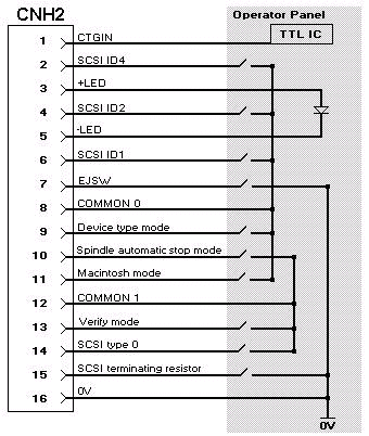
Terminal CNH 2
External operator panel connector
       Pin	Signal
        1	CTGIN (Cartridge in)
        2	-ID2 (bit value 4)
        3	+LED (+5V)
        4	-ID1 (bit value 2)
        5	-LED
        6	-ID0 (bit value 1)
        7	EJSW (Eject switch)
        8	COMMON 0
        9	Device type mode
        10	Spindle automatic stop mode
        11	Macintosh mode
        12	COMMON 1
        13	Verify Mode
        14	SCSI type 0
        15	SCSI terminating resistor
        16	0V (Ground)

The cable length to the operator panel should not exceed 30 centimetres
COMMON 0 and COMMON 1 are control signals and should not run to ground.

